


A problem was the SAW filter. S+M Siemens & Matsushita.
I finally got one, bypassing COCOM !!! I asked the manufacturer to send it to my aunt from Germany... 30 years ago.

Even I got it I used another schematic diagram for the receiver.
One model was designed by the brother of my former colleague 'CROCO' who drowned when he was student in a holiday at Black Sea. Both were known by the professor Hantila from the Electrical Engineering Faculty who trained me for admission. Mr. Hantila was a great fan of Eurosport, a program with a very weak signal in Romania, being on ASTRA satellite's spots intended for England. Other spots were for Germany, very strong signal in Romania.
The receiver designed by this Electronics faculty engineer had a PLL loop and he adjusted the bandwidth until the noise disappeared, even the image lost the fine details.
This receiver was very good for weak signals coming from medium satellite dishes.
The professor's dish was made at Targu Mures.
There they designed the bottom of the fiber glass tanks with parabolic shape !!!
It was a grey business started after 1987 when DBS started in Europe. Under Ceausescu !
Please note that the Philips technical doc above was issued on the birthday of the dictator !
An option was to buy this PLL loop receiver, but I wanted to build my receiver.
My cousin Eugen (1959-2007) worked at FEPER. His colleague Marian Ursulescu manufactured satellite receivers using a classical schematic diagram and detection with 2 Germanium diodes, like in a FM tuner ! He also manufactured the polar mounts.
I got a 1.2 meter fiber glass dish from the professor's connection, the polar mount from Marian, the LNB from Israel via Germany, a mechanical polarotor and a self-made actuator.


This is the actuator project:

The idea was a long threaded spindle attached to a windshield wiper motor. The axis was rotating thru a threaded cube nut having a bolt under, attached on the fixed part of the polar mount.
The system wasn't weatherproof but it never stuck.
The axis was made of brass and the cube was made of bronze, for minimum friction and long life.
It worked perfectly and successfully replaced a standard actuator.
I put a potentiometer on the axis of the polar mount and with a dedicated voltmeter (C520D) and a trimmer I approximated with high accuracy the azimuth of the antenna.
The polarotor has a probe inside the wave-guide. I attached a motor used for time relays and I decreased the speed by supplying with 10 Hz and U/f constant, using a sinus wave 1 transistor generator and an audio amplifier to increase voltage.

The selection of the polarity was very simple. I switched on a horizontal program, I started the motor until the signal disappeared. Then the vertical program was on its maximum level...
Finally, the receiver

Top left - input from the LNB
Inside the tin plated metal case - first intermediate frequency, second intermediate frequency, detection and video amplifier.
Under the screened part - stereo audio module
Down - S-meter, left-right audio channels tuning, multi-turn satellite channel tuning potentiometer, preset channels selector.
Top-right - power supply.
Detail:

One part was the selector, bad quality, finally I used a multi-turn potentiometer and at the end a digital tuning with sensors and memory.


The sensor tuning & memory


The oscillator


Tuning voltage 0-30 V. My design

This circuit replaced the potentiometers. Used to tune on channels and the sound carrier,
Marian's receiver schematic diagrams


I started electronics with a 35 W soldering iron. My parents bought me a soldering gun. Using a short and thick copper heating conductor I soldered the tin plated iron cases of the amplifiers, satellite receiver and all the circuits I made:


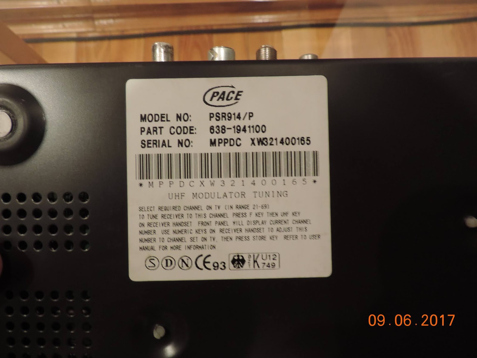
PACE 914 analogue receiver


HUMAX F1-VACI digital receiver & Viaccess decoder - March 1999


Niciun comentariu:
Trimiteți un comentariu